
Improvements Metrosoft QUARTIS R16
At a glance
Metrosoft QUARTIS R16 offers a wide range of improvements for all users and significantly contributes to optimize daily metrology work.
Metrosoft QUARTIS R16 creates automatically a measuring program from an inspection plan. Names, nominal values and tolerances are directly transferred from a list with elements and features to the measuring program. This accelerates and facilitates work and increases quality because transcription errors are prevented.
Metrosoft QUARTIS R16 contains additional measurement functionalities. Cam profiles can be scanned as 3D curves on cylinder intersections. In addition, manual measuring of borders of metal parts is simplified. The projection surface is determined automatically or selected by the user. The references of the surface, recorded in a measuring program, can be customized easily after changes in the CAD model.
Metrosoft QUARTIS R16 issues measuring results in DMO format, regardless of the execution as DMIS or QUARTIS measuring program. Therefore, the measuring values can be transferred without problems into customer-specific evaluation systems. Values for the DMO header can be read out directly from the database.
Metrosoft QUARTIS R16 offers, besides the updated CAD interfaces, many additional improvements and extensions. You find more information on the following pages.
Some improvements are not includes in the standard product Metrosoft QUARTIS R16 an require additional, chargeable modules. These are described in the document "Products and Modules Metrosoft QUARTIS R16".
Measuring program from list with elements and features (*.csv)
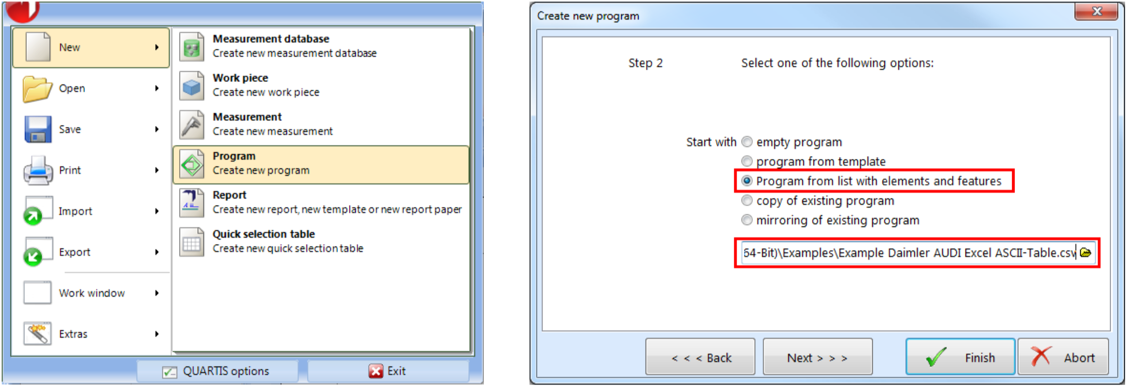
Creating automatically a new QUARTIS measuring program
You want to create automatically measuring programs from inspection plans in ASCII text file format. With Metrosoft QUARTIS R16 you can create directly a new measuring program having a list with elements and features (inspection plan). Names, nominal values and tolerances of the measuring elements are read into the measuring program. This accelerates and facilitates work and increases quality because transmission errors are prevented.
An automatically created program from a list with elements and features can be completed offline or directly on the coordinate measuring machine with alignment, report etc. If necessary, the measuring strategies of single elements can be adapted easily with “Execute program with parameter modification”.
Supported inspection plan format
Actually, the ASCII-Excel-Format (Specification of an Excel ASCII-Table to exchange feature information between CAD and CAQ Systems) defined by Daimler und Audi is supported.
Customer-specific lists with elements and features can be transferred easily into this format.
Highlights
Measurement functionalities completed and simplified
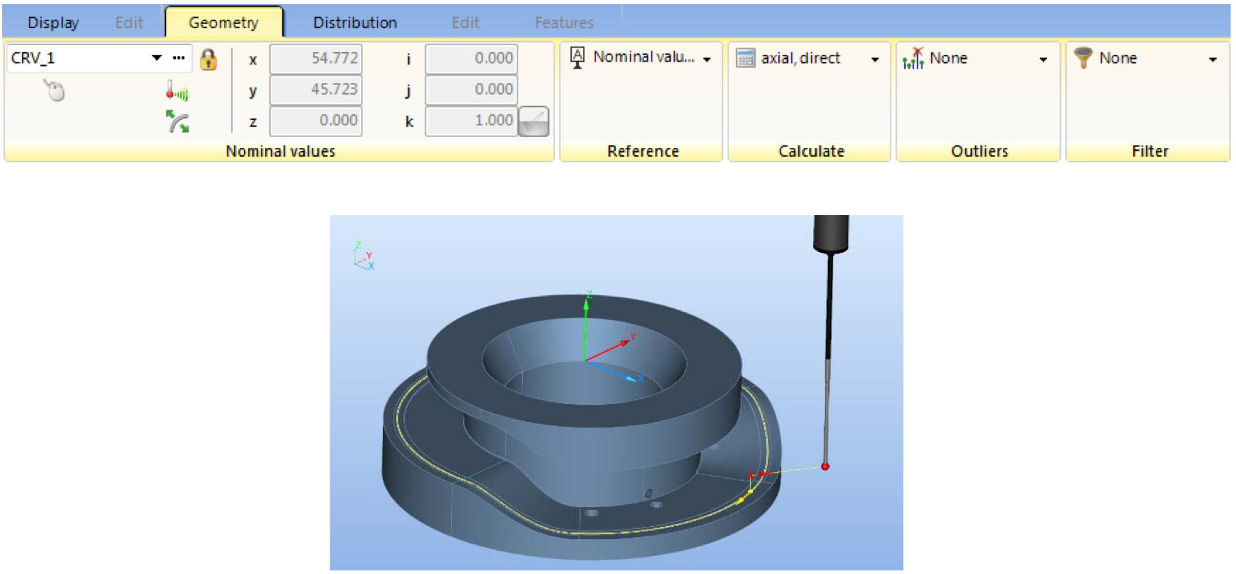
Scanning cam profile axial (3D curve on cylinder intersection)
You want to check the quality of cam profiles. For this purpose, you scan the 3D curve on cylinder intersection with the available scanning probe system.
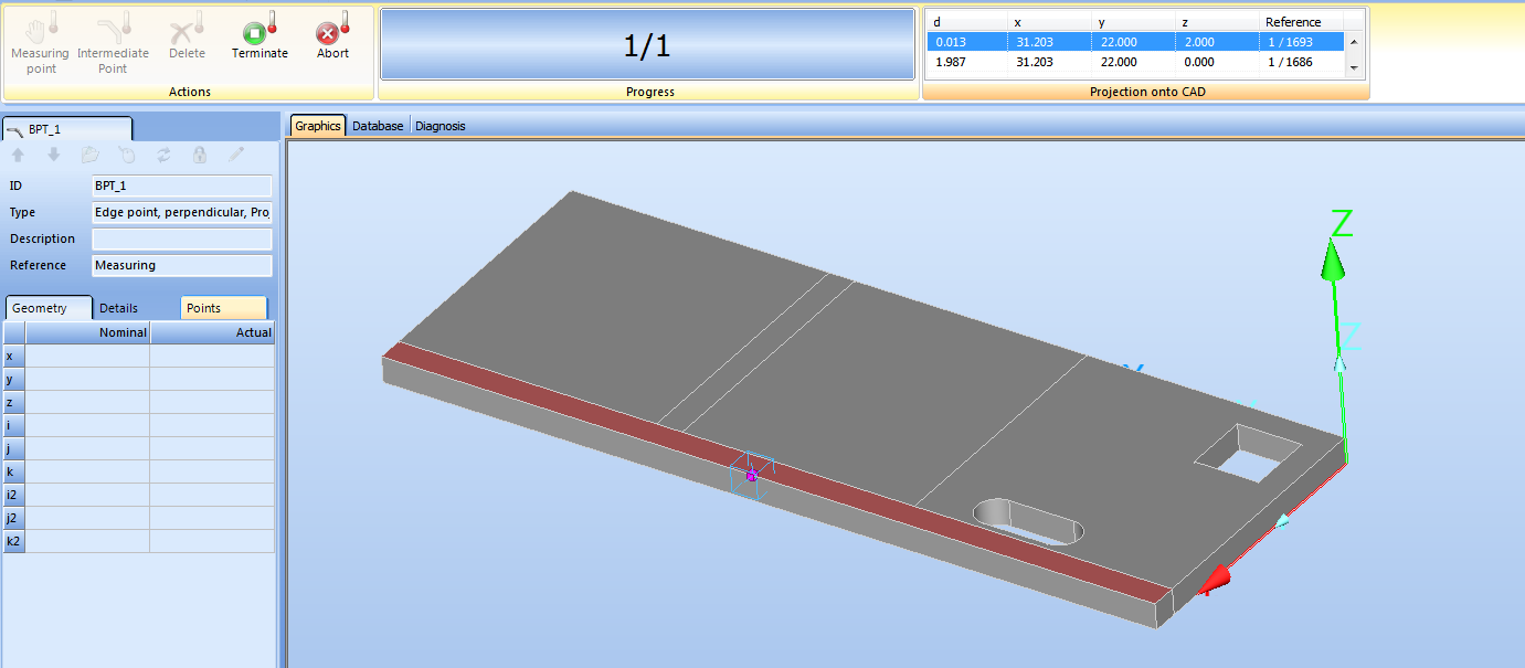
Simplified manual measuring of borders of metal parts
You measure borders of sheet metal parts on manual machines. Edge points with "Projection onto CAD" can be probed directly on the work piece without clicking the nominal value on the model before. Depending on the preseted "projection rules", the CAD surface, onto which the scanned edge point is projected, is determined automatically or selected by the user out of a list.
References of surfaces, recorded in a measuring program, can be customized easily and referenced newly with "Selective parameter modification".
Highlights
Output of measuring results in DMO format
Writing DMO file during execution of QUARTIS measuring program
You need the measurement results in a standardized DMIS output format (*.dmo), in order to read in these results into a higher-level evaluation system or deliver these results to your customers.
When running DMIS programs, DMO result files have always been created according to the corresponding DMIS statements. Newly, the measurement results can also be written into DMO files when executing QUARTIS measurement programs.

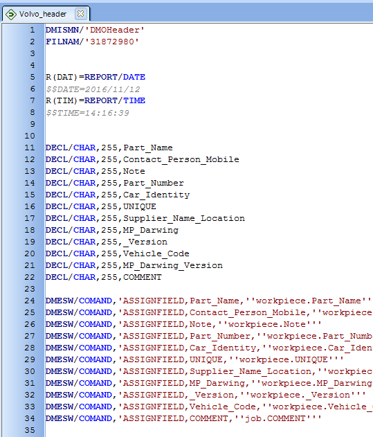
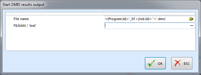
Creating header data (DMO header)For the data transfer in evaluation systems, the customer usually needs precisely defined header data. These data can be written easily and flexible into a DMO file via the corresponding DMIS program, which is embedded as subroutine in a QUARTIS measuring program. Already existing values in the measurement database are transferred automatically into the DMO file. The DMIS statement “FILNAM / ‘text’” is often used for identification of the measuring result. The content of the variable ‘text’ can be entered as text or expression when recording the function “DMO Start”. |
|
Highlights |
|
More improvements
In Metrosoft QUARTIS R16 are numerous additional helpful functions available:
- Following CAD interfaces were updated to the newest version:
- CATIA V5 (R8 to R2017)
- CATIA V6 (to R2017)
- Siemens NX (NX1 to NX11)
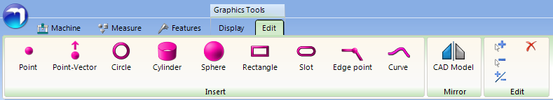
- SolidWorks (2003 bis 2017) – 2015 and higher only available in 64-Bit QUARTIS - You want to insert auxiliary elements into the CAD model as preparation for measurement to execute efficiently and reproducibly a measurement task. Newly, you can insert the elements Circle, Cylinder, Sphere and Edge point with different methods.
- The DMO file is written when executing the DMIS statement “CALL/EXTERN,SYS,...” as with “CALL/EXTERN,DME,...”. This ensures that the DMO file is available in a called “External program”.
-
You are working on WENZEL measuring machines and also want to measure gears. WENZEL WMC controlling with Renishaw sensors SP25, SP600 und SP80 is supported.
- The construction ”Min/Max element” is operated via the ribbon, which offers numerous benefits.
-
When measuring with the WENZEL PHOENIX II Sensor, you can activate/deactivate the sensor image preview in the program sequence. This increases the comfort of program controlled, manual measurements and the lifetime of the sensor.
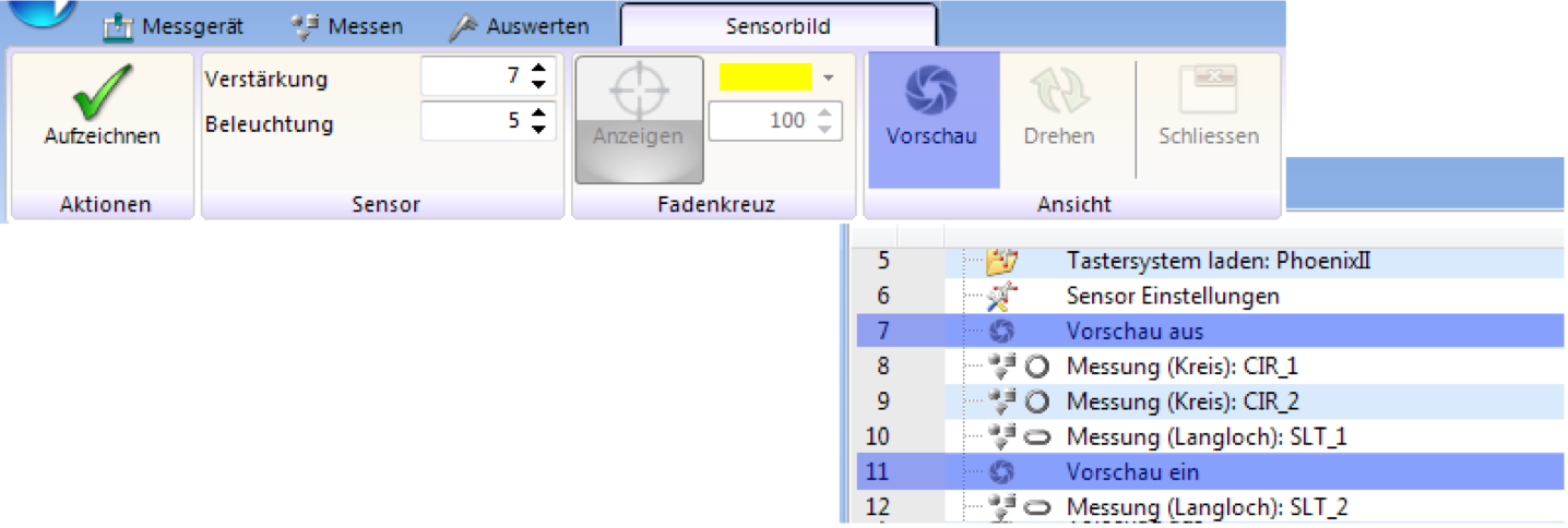 Users can recognize better, whether the PHOENIX II live image is displayed in QUARTIS. Thereby usage is safer and easier.
- More WENZEL machine models and dimensions can be configured for displaying in 3D graphics. Following machine models were added:
- WENZEL LH (3G) 1512 (2000, 2500, 3000)
- WENZEL RSplus 1615 (16000)
- WENZEL RSplus 1825 (10000)
- WENZEL LHF (3G) 3020 (4000, 5000, 6000, 7000)
- WENZEL LHF (3G) 4025 (4000, 5000, 6000, 7000) - Bitmap images inserted in reports are automatically compressed, which increases performance.
- Storage location and name of the report paper used in the report are displayed in the program details of “Create report”.
- You use your machine in an automated production process (Industry 4.0) and want to monitor Metrosoft QUARTIS with an external program. For this purpose, the automation interface is equipped with event messages. Communication takes place via the TCP based protocol MQTT.
- You must connect Metrosoft QUARTIS with a Renishaw UCC server in offline mode when programming offline with Renishaw REVO or PH20, in order to simulate the 5-axes moves of the probe heads correctly. For this constellation, the work piece can now be positioned in the 3D graphics on the CMM.
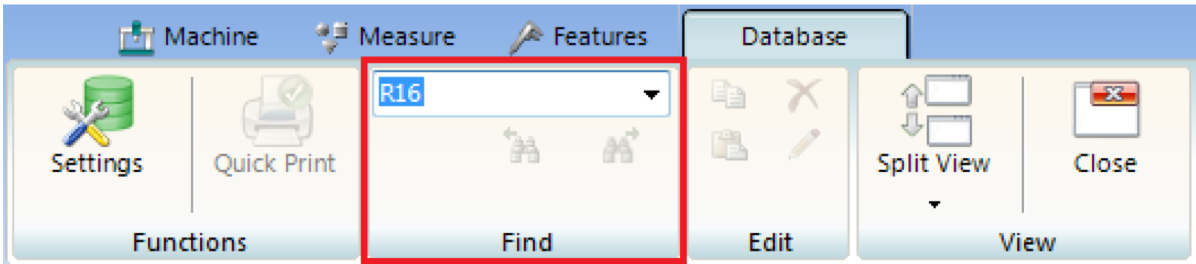
- You have many work pieces, programs, measurements and other data in your database. The new database find function will simplify and shorten your work.
- You use Metrosoft QUARTIS in a noisy industrial environment. The audio files (QUARTIS sounds) have been optimized. The level of the audio files has been raised. The sound is purer and louder as in earlier versions.
- Measurement databases now can be converted using batch mode. This significantly reduces the workload and saves time during update to a new Metrosoft QUARTIS version for customers with many measurement databases.